
White Noise Sample-and-Hold my Beer Part II: Summer Breeze Makes me Feel Fried
This is part II of a two-part post detailing one of my Summer projects: The YASH Redux. YASH Redux is a sample-and-hold circuit driven by white noise with portamento and a test oscillator for fine-tuning and troubleshooting. You can find Part I here!
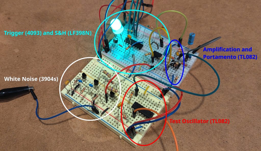
As outlined in Part I, this circuit came out of a (naive) desire to quickly prototype a ramp noise circuit for use with the Koma Elektronik Field Kit/FX. It turns out there’s a lot more to a functional S&H circuit than the S&H part. You need a noise source, a trigger for the S&H chip, scaling depending on your noise source amplitude and your power-supply values, and 100% something to test your in-progress chip on.
The YASH circuit by René Schmitz is a really nice, easy circuit that uses the LF398 S&H chip which does the dirty work of, well, the sample-and-hold. I also consulted Jeremy Long’s Eurorack version of the YASH when putting together that part of the circuit. I didn’t really need to make any changes to those circuits, and, despite some of the resistors being unnecessary/redundant, left that portion of the circuit as-is.
For the White noise generator, I used the three transistor white noise circuit from Ray Wilson’s Analog Synths book. I already had the circuit made, so that was a pretty easy decision. I’ll skip any blue language about the “one Zener diode white noise” circuits you will find in the wild and simply recommend you avoid them and try this one instead. It’s three 3904 transistors and some resistors. Easy peasy and sounds great.
There’s not too much more to the circuit. I use a TL082 for both amplification and portmento and a second 4093 chip for a test oscillator. It’s a waste of 3/4 of the 4093, but I have a bunch laying around so I used what was on-hand. Feel free to substitute with your oscillating IC of choice.
Super Brief Video Overview
Below is a brief video demo of the prototype.
Files
The files for this project (schematic, BOM, etc) are on my GitHub: https://github.com/scottericpetersen/yash-redux
Things to Have (if you want to try this circuit out)
- A bench power supply with 12V DC minimum. Better a dual rail ±12v supply.
- An oscilloscope *you know how to use*
- With or without an oscilloscope, a test oscillator (circuit included here!) will be invaluable. Multimeters can help with steady-state values, but this circuit often moves too fast for the meter and it’s easier to hear what’s happening than guess based on a scope or meter. But maybe that’s just me.
- A multimeter for determining your important DC values (at TL082 pin 3, for example.)
Features
- White Noise w/~2.5v peak-to-peak output amplitude
- Sample and hold with adjustable trigger speed controlled by a potentiometer
- Adjustable portamento (smoothing) of the output (step -> ramp)
- optional test and troubleshooting oscillator
S&H Schematic
Key Circuit Features
There are a number of components whose values that have considerable effect on the resulting output as evidenced in the video above. These are essentially the “tunable” components. Exactly how their values affect the circuit is detailed somewhat below. Several are probably appropriate for a potentiometer, especially R13 – the resistor that is part of the portamento “amount” equation.
RV1 (1M pot) — trigger/sample rate. Sets how often the S&H grabs a new random value. In the YASH, it is an optional tie-in to a manual or trigger input from another source. I’ve just hard wired it as I don’t need or want another input – I just want this to fire off at regular intervals.
C3 (470nF, gate D) — trigger oscillator’s overall rate range. This cap scales RV1’s whole tunable range up or down, independent of where RV1 itself is set.
LF398 hold cap (C7, on pin 6) — how well the sampled voltage holds between triggers. Too small and you get a voltage drop during the hold (a droop?). You would probably not want to change this, but knowing it’s there is good. I might actually increase this from 0.1uF, but I haven’t tested it yet.
C9 (now 4.7µF) / R13 (10k-100k) — portamento amount. By adjusting the R and C values here the sample-and-hold steps can be crisp to entirely negated. With R13 at 10k and C9 <1µF, the step-hold relationship is quick and crisp with almost no noticeable portamento. Adjust C9 to something like 4.7µF and there is noticeable portamento where the hold time is minimal. Adjust C9 to 10µF and increase R13 to 20k and the effect will be to almost negate any swing around the center of the noise range, resulting in a slowly modulating frequency ramp.
R14 (47k) — Test oscillator’s center frequency range. This controls the frequency *around which* the randomness occurs. You can make this slightly higher and slightly lower to shift the test oscillators center frequency, but it’s not really necessary and doesn’t affect the S&H output – just what you hear.
R15/R16 (~8k/10k) — voltage divider, biases input low or high depending on relationship. When properly DC filtered, this should be 10k/10k. But if your output seems biased low or high, adjust these. Mine is obviously DC biased so I made this quick calculation by ear rather than troubleshoot the circuit anymore.
Wrap it up, B!
The YASH Redux is still a work in progress in that there is some fine-tuning to be done to values to maximize the quality of the results. However, the circuit is stable and works as expected, albeit with a limited range due to to the power-supply constraints (mentioned above.) Will I continue work on it? Maybe, but there are always both newer and older projects to work on and I think this one has run it’s course.
A sneaky complaint right at the end
Creating circuit diagrams is awful. Fortunately, I have just the right amount of OCD to be able to stand the ultra-faffy interface of KiCad. I tried *everything* else when figuring out what to use, and honestly, this is the way to go. All of the parts you need (for this project, anyway) are in the standard library and, provided you *want* or need validation and eventual PCB design, KiCad does it all. The interface is finicky and making connections and dragging/moving objects is incredibly annoying. I had to keep zooming in and out to figure out what was going on. That said, everything is also very portable (it **can** move and maintain connections — or not) and customizable.
Links
Transistors and other basic components are easy enough to learn and understand, and chips like the LF398 used in this project are specific enough that the datasheet/AI can give you the basics. If you are just getting into electronics for audio or composition, learning the basics of operational amplifiers (opamps) will be very helpful because they are used everywhere and have many applications. The tutorials below are nice introductions with a pretty good balance of detail (snore) and overview.
Good tutorials on operational amplifiers here: https://www.electronics-tutorials.ws/opamp/opamp_1.html
Some related tutorials (same source) on necessary theory/operation of opamps: https://www.electronics-tutorials.ws/systems/electronic-system.html